
Example Calculation of the Life Expectancy of a Profiled Rail System
Problem:
During the designing phase of a project, a team considered using a profiled rail system in order to support a load. Given the following information about the system, determine the life expectancy of the runner block in work hours.
Known:
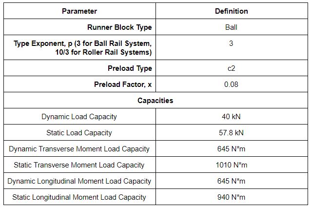
Runner Block Specifications
Model: R1653 721 20
Profiled Rail Type: Ball Rail
Size Specification: 30
Preload Class: C2
Capacities
Dynamic Load Capacity: 40 kN
Static Load Capacity: 57.8 kN
Dynamic Transverse Moment Load Capacity: 670 N*m
Static Transverse Moment Load Capacity: 1010 N*m
Dynamic Longitudinal Moment Load Capacity: 645 N*m
Static Longitudinal Moment Load Capacity: 940 N*m
Layout of the System
Number of Runner Blocks: 1
Number of Guide Rails: 1
Position of the Runner Block:
- X-Coordinate: 0 mm.
- Y-Coordinate: 0 mm.
- Z-Coordinate: 0 mm.
Position of the Drive Unit
- X-Coordinate: 0 mm
- Y-Coordinate: -100 mm
- Z-Coordinate: -25 mm.
Total Mass of the System: 400 kg.
Center of Gravity of the System:
- X-Coordinate: 0 mm
- Y-Coordinate: 100 mm
- Z-Coordinate: 50 mm.
Dynamic Cycle and Loading
The system travels in two strokes, one stroke in the positive X-direction and one stroke in the negative X-direction. Each stroke has three phases:
- Acceleration Phase: The profile rail travels from rest at a constant acceleration of 2.5 meters per second squared for a duration of 1 second. During this phase, there is no load on the runner block other than the runner block’s weight and the force on the runner block due to the acceleration.
- Constant Velocity Phase: The runner block travels at a constant velocity for a duration of 2 seconds. In the forward stroke of the runner block, the system experiences a load of 25 Newtons in the positive y-direction during the constant velocity phase. On the reverse stroke, the runner block experiences no load on the runner block other than the runner block’s weight and the force on the runner block due to the acceleration.
- Deceleration Phase: The profile rail travels at a constant deceleration of -2.5 meters per second squared for a duration of 1 second. At the end of the deceleration phase, the runner block is at rest. During this phase, there is no load on the runner block other than the runner block’s weight and the force on the runner block due to the acceleration.
The figures below better demonstrates the motion of the runner block:
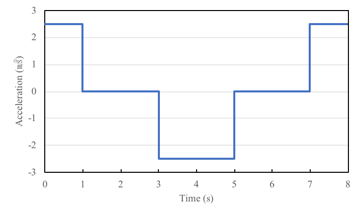
Acceleration of the Runner Block over time during the cycle
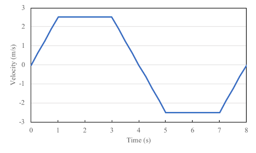
Velocity of the Runner Block over time during the cycle
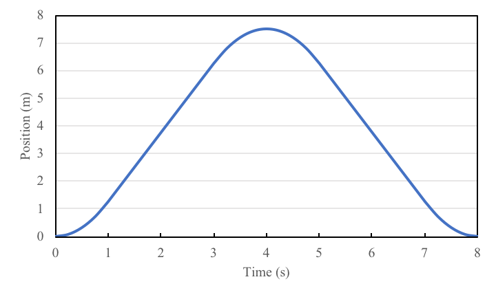
Runner Block Distance from Starting Position Over Time during the cycle
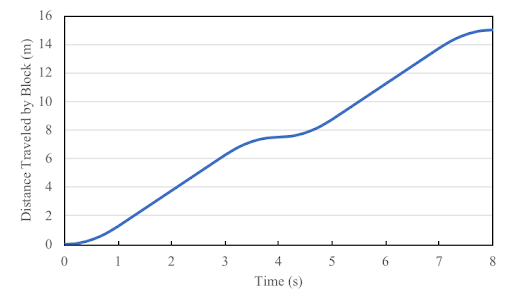
Total Distance Traveled by Runner Block over time during the cycle
Calculations
Step 1: Define Parameters
Parameters – Runner Block
Parameters – Phases
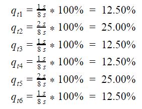
Discrete Travel Steps – The percentage of the total travel of the runner block at each phase.
The runner block travels a total of 15 m during one cycle, therefore the travel steps for each phase are:
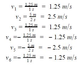
Average Velocities – The average velocity traveled at each phase. Is given as the ratio of the distance covered in each phase to the amount of time to complete the phase. The average velocities for each phase are:
Parameters – Load Cases:
Case 1: Weight
The weight of the system is present throughout the entire cycle. The weight of the system is:
Fg= 40 kg * 9.81 m/s2 = 392.4 N in the negative Z-direction
Case 2: Process Force
The process force was defined in the introduction as the 500 N force in the positive y-direction. Therefore, the process force is:
Fp=500 N in the positive Y-direction
Case 3 and 4: Acceleration/Deceleration Forces
The acceleration force is the force on the runner block due to accelerating or decelerating. Due to the runner block’s inertia, the acceleration force is considered to be in the opposite direction of the acceleration. The magnitude of the acceleration/deceleration during phases 1, 3, 4, and 6 are all 2.5 meters per second squared. Therefore the magnitude of the acceleration forces are all:
40 kg * 2.5 m/s2 = 100 N
For phases 1 and 6, the acceleration force is in the negative X-direction.
For phases 3 and 4, the acceleration force is in the positive Y-direction.
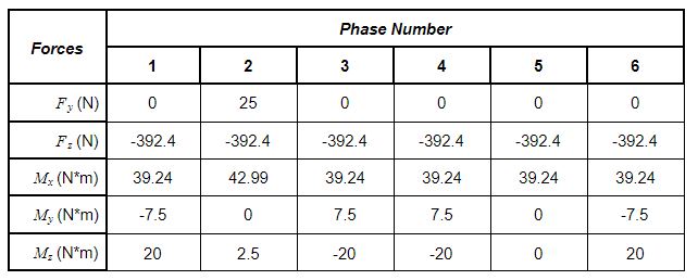
Step 2: Determination of the Load Reactions on the Runner Block
Based on the layout and the loads given, the following load reactions can be determined. For more information on how to calculate the load reactions, (insert location of page containing formulas)
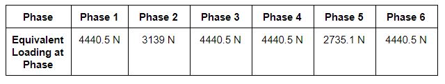
Step 3: Determination of Equivalent Loads
Based on the reactions, equivalent loads for each of the phases can be determined as the following:
Step 4: Determination of the Effect of Preload on the Loads.
To determine if the preload has any effect on the loads, the preload and lift-off forces needs to be determined. The preload force is equal to the preload factor (0.08) multiplied by the dynamic load capacity of the runner block. The lift off force is equal to 2.8 times the preload force.
The lift-off force for the runner block is:
Fpr= 0.08*40000 N = 3200 N
Fli= 2.8*3200 N = 8960 N
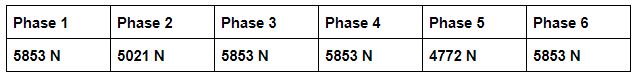
Since all the equivalent loads are smaller than the lift-off force, the pre-load does have an effect on loading. The equivalent loads at each phase, taking into account the pre-load are:
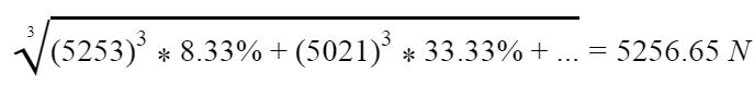
Step 5: Calculation of Total Equivalent Load on Bearings
Using the results from Step 4, the total equivalent load on the bearings of the runner block can be determined as:
Step 6: Determination of the Life Expectancy
Using the result from step 5, the life expectancy for the runner block with a 90% reliability can be calculated as:

If, after discussion, the team had decided that the team needs a reliability of 95% instead, the effect that the reliability has on the load needs to be taken into account. The life expectancy of the runner block with a 95% reliability can be calculated as:
![]()
In industry, it is usually more important to know the life expectancy of the runner block in work hours. The life expectancy of the runner block in work hours, with a 95% reliability can be calculated as:
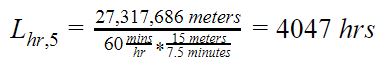
This concludes the example calculation of the life expectancy of the runner block.


