
Brushed DC Motors
Direct-current motors are used where a wide range of precise torque and speed control is required to match the needs of the application. Such applications include cranes, conveyors, and elevators. Direct-current motors are not used as much as alternating current types because all electric utility systems deliver alternating current. For special applications, however, it is advantageous to transform the alternating current into direct current in order to use DC motors.
The construction of a DC motor is considerably more complicated and expensive than that of an AC motor, primarily because of the commutator, brushes, and armature windings. Maintenance of the brush/commutator assembly found on DC motors is significant compared to that of AC motor designs. An AC induction motor requires no commutator or brushes, and most use cast squirrel-cage rotor bars instead of wound copper wire windings. There are several types of DC motors, classified according to field type. These are permanent magnet, series, shunt, and compound.
Motor speed, torque, and power are important parameters used to predict DC motor performance:
Speed: Refers to the rotational speed of the motor’s shaft and is measured in revolutions per minute (rpm).
Torque: Refers to the turning force supplied by the motor’s shaft. Torque consists of force acting on a radius. The standard unit of torque is Nm.
Power: Refers to the rate at which work is done. It is usually stated in horsepower. One horsepower is equivalent to 746 watts of electrical power. Therefore, you can use watts to calculate horsepower and vice versa.
Permanent-Magnet DC Motors
Permanent-magnet DC motors use permanent magnets to supply the main field flux and electromagnets to provide the armature flux. Movement of the magnetic field of the armature is achieved by switching current between coils within the motor. This action is called commutation. Brushes, in contact with the commutator, carry current to the coils. PM motors produce high torque compared to wound-field motors. However permanent magnet motors are limited in load-handling ability and for this reason used mainly for low-horsepower applications. The direction of rotation of a permanent-magnet DC motor is determined by the direction of the current flow through the armature. Reversing the polarity of the voltage applied to the armature will reverse the direction of rotation. Variable-speed control of a PM motor is accomplished by varying the value of the voltage applied to the armature. The speed of the motor varies directly with the amount of armature voltage applied. The higher the value of the armature voltage, the faster the motor will run.
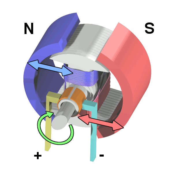 Workings of a brushed electric motor with a two-pole rotor (armature) and permanent magnet stator
source: https://commons.wikimedia.org/wiki/File:Electric_motor_cycle_2.png
Wound-field DC Motors
Wound-field DC motors are usually classified as:
- Series-wound
- Shunt-wound
- Compound-wound
Series DC Motor
A series-wound DC motor has a low resistance field and low resistance armature circuit. Because of this, when voltage is first applied to it, the current is high (I = E/R). The advantage of high current is that the magnetic fields inside the motor are strong, producing high torque (turning force), so it is ideal for starting very heavy mechanical loads. The speed varies widely between no load and rated load. Therefore, these motors cannot be used where a constant speed is required with variable loads. Also the motor runs fast with a light load (low current) and runs substantially slower as the motor load increases. Because of their ability to start very heavy loads series motors are often used in cranes, hoists, and elevators, which can draw thousands of amperes on starting. Caution: The no-load speed of a series motor can increase to the point of damaging the motor. For this reason, it should never be operated without a load of some type coupled to it.
Shunt DC Motor
When the motor is starting and speed is very low, the motor has very little torque. After the motor reaches full rpm, its torque is at its fullest potential. One of the main advantages of a shunt motor is its constant speed. It runs almost as fast fully loaded as it does with no load. Also, unlike the series motor, the shunt motor will not accelerate to a high speed when no load is coupled to it. Shunt motors are particularly suitable for applications such as conveyors where constant speed is desired and high starting torque is not needed.
Compound DC Motor
A compound-wound DC motor is a combination of the shunt-wound and series-wound types. The shunt field gives this type of motor the constant-speed advantage of a regular shunt motor. The series field gives it the advantage of being able to develop a large torque when the motor is started under a heavy load. This motor is normally connected cumulative-compound so that under load the series field flux and shunt field act in the same direction to strengthen the total field flux. These motors are generally used where severe starting conditions are met and constant speed is required at the same time.
DC Servo Drives
The precise meaning of the term ‘servo’ in the context of motors and drives is difficult to pin down. Broadly speaking, if a drive incorporates ‘servo’ in its description, the implication is that it is intended specifically for closed-loop or feedback control, usually of shaft torque, speed, or position. Early servomechanisms were developed primarily for military applications, and it quickly became apparent that standard DC motors were not always suited to precision control. In particular high torque to inertia ratios were needed, together with smooth ripple-free torque. Motors were therefore developed to meet these exacting requirements, and not surprisingly they were, and still are, much more expensive than their industrial counterparts. Whether the extra expense of a servo motor can be justified depends on the specification, but prospective users should always be on their guard to ensure they are not pressed into an expensive purchase when a conventional industrial drive could cope perfectly well. The majority of servo drives are sold in modular form, consisting of a high-performance permanent magnet motor, often with an integral tachogenerator, and a chopper-type power amplifier module. The drive amplifier normally requires a separate regulated DC power supply, if, as is normally the case, the power is to be drawn from the AC mains. Continuous output powers range from a few watts up to perhaps 2–3 kW, with voltages of 12, 24, 48, and multiples of 50 V being standard.
Position control
As mentioned earlier many servo motors are used in closed-loop position control applications, so it is appropriate to look briefly at how this is achieved. In the example shown in figure, the angular position of the output shaft is intended to follow the reference voltage (uref), but it should be clear that if the motor drives a toothed belt linear outputs can also be obtained. The potentiometer mounted on the output shaft provides a feedback voltage proportional to the actual position of the output shaft. The voltage from this potentiometer must be a linear function of angle, and must not vary with temperature, otherwise the accuracy of the system will be in doubt. The feedback voltage (representing the actual angle of the shaft) is subtracted from the reference voltage (representing the desired position) and the resulting position error signal is amplified and used to drive the motor so as to rotate the output shaft in the desired direction. When the output shaft reaches the target position, the position error becomes zero, no voltage is applied to the motor, and the output shaft remains at rest. Any attempt to physically move the output shaft from its target position immediately creates a position error and a restoring torque is applied by the motor.
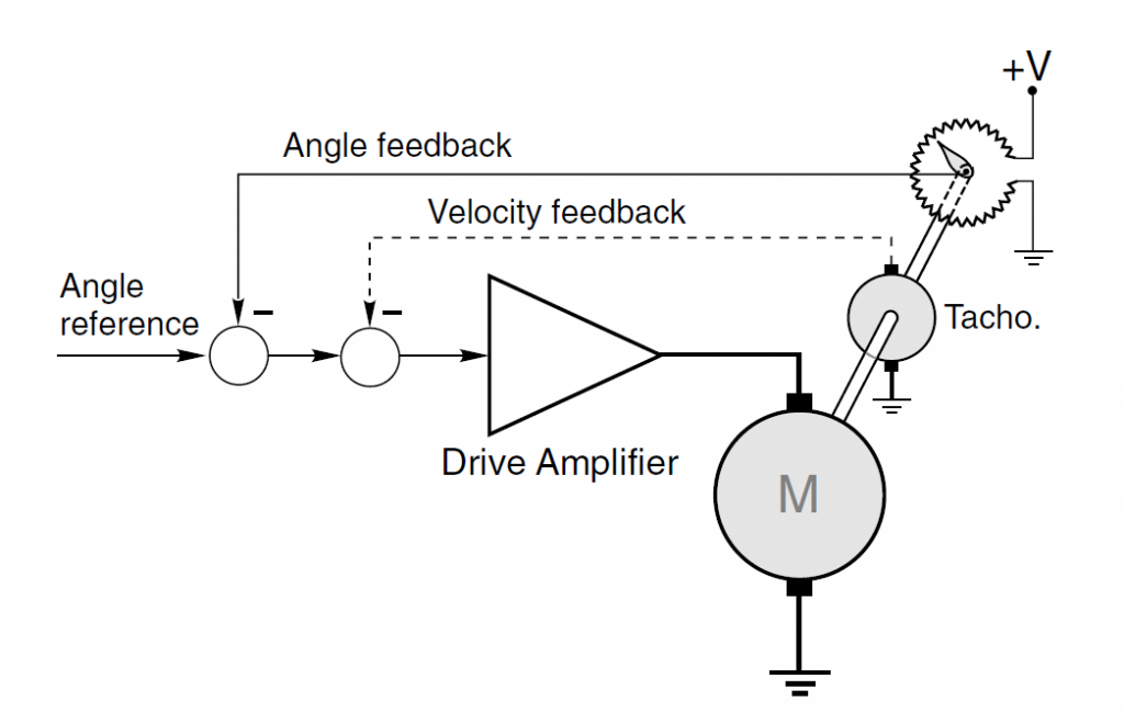
Closed-loop angular position control using DC motor and angle feedback from a servo-type potentiometer
Source: Electric Motors and Drives by Austin Hughes
Control arrangements for DC drives
The most common arrangement, which is used with only minor variations from small drives of say 0.5 kW up to the largest industrial drives of several MW, is the so-called two-loop control. This has an inner feedback loop to control the current (and hence torque) and an outer loop to control speed. When position control is called for, a further outer position loop is added. A two-loop scheme for a thyristor DC drive is discussed first, but the essential features are the same in a chopper-fed drive.
In order to simplify the discussion we will assume that the control signals are analogue, although in all modern versions the implementation will be digital, and we will limit consideration to those aspects which will be beneficial for the user to know something about. In practice, once a drive has been commissioned, there are only a few adjustments to which the user has access.
To appreciate the overall operation of a two-loop scheme we can consider what we would do if we were controlling the motor manually. For example, if we found by observing the tachogenerator that the speed was below target, we would want to provide more current (and hence torque) in order to produce acceleration, so we would raise the armature voltage. We would have to do this gently, however, being mindful of the danger of creating an excessive current. We should keep our eye on the ammeter at all times to avoid blowing up the thyristors; and as the speed approached the target, we would trim back the current (by lowering the applied voltage) so as to avoid overshooting the set speed. Actions of this sort are carried out automatically by the drive system.
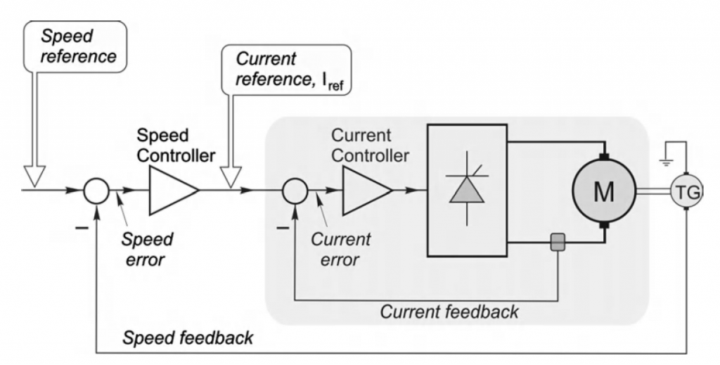 Schematic diagram of analogue controlled-speed drive with current and
speed feedback control loops
source: Electric Motors and Drives by Austin Hughes
A standard DC drive system with speed and current control is shown. The primary purpose of the control system is to provide speed control, so the ‘input’ to the system is the speed reference signal on the left, and the output is the speed of the motor (as measured by a tachogenerator) on the right. As with any closed-loop system, the overall performance is heavily dependent on the quality of the feedback signal, in this case the speed-proportional voltage provided by the tachogenerator. It is therefore important to ensure that the tacho is of high quality (so that, for example, its output voltage does not vary with ambient temperature, and is ripple-free) and as a result the cost of the tacho often represents a significant fraction of the total cost.


