Procedures
SUMMARY
This research evaluated and quantified the performance and effectiveness of pre-applied wetting agents in prevention of wildland fire spread to landscaping plants and structures in the wildland urban interface… The project evaluated the fire performance of three categories of wetting agents (water, Class A foams and gels) on landscaping vegetation fuels surrounding structures and external structural materials, and assess the effectiveness of these wetting agents on ignition and fire spread prevention. The wetting agents were applied at various times prior to exposure fire conditions, and exposed to various drying conditions to evaluate their performance as a function of time and drying conditions that might be encountered prior to the fire front arrival to account for water evaporation and run off.
The evaluation and assessment was achieved through the determination of Critical Flux for Fire Growth (CFFG) on individual landscaping plants and building assemblies within three minutes of the heat flux (heat radiation) exposure from a radiant panel. The Intermediate Scale Calorimeter was used to provide the heat flux exposure. The CFFG was found by exposing the samples to varying heat fluxes until the flux was just sufficient to ignite and start fire growth within three minutes of exposure. The plants and the building assemblies were simultaneously exposed to a 300 mm pilot flame. The heat flux exposure simulated radiation exposures from wildfires, and the pilot flame simulated flaming from accumulated embers and other small fires started by embers and flying brands. The three minute exposure was used to simulate the relatively fast fire front passage time. .
The results of the intermediate-scale laboratory tests were then verified on a series of full-scale outdoor tests.
Data collected from these tests was used to develop a standard test method for evaluating UWI wetting agents on various substrates. The test method is currently being developed into an ASTM standard.
In addition, an educational module was developed that is herein being disseminated to fire services within North Carolina and nationwide. The fire service and building owners can immediately transfer the research results into special wetting agent purchasing decisions and firefighting tactics related to the use of wetting agents to increase the level of firefighter safety involving UWI fires.
EXPERIMENTAL
Intermediate Scale Tests
A survey was conducted among 10 nurseries in the southeastern states of the U.S with the objective to determine the most popular landscaping plants in this part of the country. Nine plants were selected for this research based on the results of the survey. One plant (Hollywood Juniper) was selected from the plants tested by Ettlinger10 who tested plants used in California, and found that this plant had the highest burning rate. The plants included in this project and the volume of the container and approximate plant dimensions are given in Table 1.
The plants were purchased in a local nursery. The plants chosen were the largest available at that facility. The plants were dried to about 25 % of the total plant water content, which represented barely alive plants representative of the worst case condition the plants would be in during a drought10. For comparison, one plant was dried completely, which represented about 10 % of the total plant water content (Compacta Holly). The plants’ water content was determined by weighing branches of the plants during the drying process. It was noticed that several plants dried non-uniformly, which might possibly affect the results of the measurements. However, it is not necessary that in nature the plants would always dry uniformly so this is only a limitation to consider.
Table 1 Plant Sample Selection and Conditioning

External Wall and Roof Constructions
The assembly used to test the building structures were to be created to be representative of those found commonly across the country. The external wall and roof assembly specimens (building materials) were 1000 mm x 1000 mm large. They were constructed by fastening a 12.7 mm thick oriented strandboard for walls and 19 mm thick oriented strandboard for roofs onto a wood frame made of 38 mm x 89 mm wood boards with two additional boards spaced evenly between the upper and lower frame member. The frame was made so that the shorter sides of the boards were attached to the oriented strandboard. The oriented strandboard was covered with a plastic vapor barrier for the wall assemblies and bituminous paper for the roof assemblies on which either the siding or the roofing materials were attached following the manufacturers’ installation instructions. The siding materials were a solid sheet of white color painted (the paint was latex based) 12.3 mm thick plywood siding and vinyl siding, with the vinyl sections installed horizontally according to the manufacturer’s instructions. The roofing materials were the U.S. common asphalt shingles and wood shakes installed according to the manufacturer’s instructions. The installations were designed to represent the common building construction in the United States. All the siding and roofing materials were purchased from a local building supplier. The specimens were conditioned at 50 ±10% humidity and 20 ±5 °C to constant weight.
Wetting Agent Application and Testing Procedure
The plant specimens and building materials were prepared and tested first without any wetting agents and then with each of the wetting agents considered, water, foam, and gel. The water wetting agent was from the municipal supply and sprayed using a garden hose sprayer. The time of water spray application was one minute, which was found sufficient to obtain the maximum retention of the water on the plants. The foam was “type A” foam applied using a portable self contained system specifically designed for foam application. The settings of the system were adjusted so that the quality of the foam typically used in the field was achieved. The foam was applied to the plants from two sides to obtain the foam coverage on the plants as uniform as possible. The gel used was from a single manufacturer. It was applied using a commercially available home use applicator provided by the manufacturer. The gel was applied at the quantity as high as possible and according to the manufacturer instructions. The application of the wetting agents was practiced to achieve the coverage as repeatable as possible before actual testing on the specimens occurred. However, some variability of the wetting agents on the plants was impossible to avoid again which mimics actual circumstances. The soil surface and the containers were protected with plastic foil before the wetting agents were applied, and the protection was removed before the plants were placed in the testing position. The application of the wetting agents on the building material specimens was similar as on the plants. However, the repeatability and uniformity of the application was better than for the plants.
Four different conditions were used on all the specimens which were to be investigated:
- Conditioned or dried without wetting agent application,
- Testing to be done within 10 minutes of the wetting agent application,
- In one hour after wetting agent application or at a shorter time if it was found in a test that most of the wetting agent had evaporated by that time,
- In one hour after wetting agent application while the specimens were exposed to a one kW/m2 irradiance and nine m/s wind, simulating high heat drought conditions. In some cases a shorter times of exposure were used if it was found in a test that most of the wetting agent had evaporated by that time.
For each condition and each specimen a Critical Flux for Fire Growth (CFFG) was determined using the bracketing procedure explained below. Typically, it was required to conduct three to five tests for each condition to determine the flux that supported fire growth on a specimen in about three minutes after the exposure. Two more replicate tests were subsequently conducted to confirm the results.
The test apparatus used to provide radiation exposure was the Intermediate Scale Calorimeter (ICAL)11. This apparatus provided a uniform and constant radiation heat flux onto a 1 m x 1 m vertical area in front of the radiant panel. The plant specimens were positioned on the weighing with the plastic container protected with a noncombustible board positioned between the plants and the radiant panel. The desired radiation heat flux exposures were achieved by adjusting the distance between the radiant panel and the specimens. The plants were positioned so that the desired radiation heat flux was on the plant branches closest to the radiant panel. A 300 mm high pilot flame from a 10 mm inner diameter copper tubing burner was used as the ignition source. The pilot flame size was chosen as a simulation of accumulated burning brands and ambers that sometimes arrive ahead of the wildfire flame front. In absence of any literature information on the size of the pilot flame, a size used was considered a conservative representation of possible urban wildland interface ignition sources. The pilot flame was relatively large, and typically ignited the plants around the flame in most tests. For the purpose of this project, the specimens were considered to have ignited when the fire growth in the form of flame spreading through the plants was observed (note that only the side of a plant closest to the radiant panel was exposed to the desired heat flux. The rest of plant received a lower heat flux due to a larger distance from the radiant panel, and because if was shielded from the heat flux by its own leaves and branches. The pilot flame was positioned just above the top edge of the plant container with the flame directed approximately into the front area of the plants.
The same pilot flame was applied to the building material specimens. The burner tubing end was located centrally about 50 mm above the bottom edge of the specimens, and with the closest part of the burner about 12 mm from the specimen surface. The flame was directed at about 45 ° angles toward the surface and was impinging on the surface. A typical experimental setup of a plant specimen is shown in Figure 1, and a typical setup of an external wall or roof assembly is shown in Figure 2.
All the tests were conducted by placing the specimens either on the weighing platform (plants) or into the standard ICAL sample holder (building materials). The ignition burner was lit for about five seconds before the shield that protects the specimens was removed exposing the specimen to a desired radiation heat flux. Observations were made of the time when the fire on the specimen started to grow. If the fire growth was observed before the expiration of three minute time (±30 s) of the start of the test the radiation heat flux was decreased and the test was repeated. If no fire growth occurred within three minutes, the test was repeated at a higher radiation heat flux. After the radiation heat flux was determined, which led to ignition at about three minutes, the tests at the determined flux were repeated at least two more times. If significant deviations from the radiation heat flux determined in the first test were found, the radiation heat flux was adjusted, and additional tests were conducted to determine the CFFG.
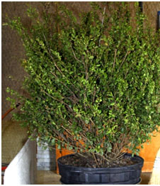 Figure 1 Experimental setup for plant test (Compacta Holly without wetting agent)
 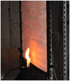 Figure 2 Experimental setup for a wall assembly test (Vinyl siding with gel)
The three minute time was a conservative assumption of the time of the wildfire flame passage time. This was based on the work of Cohen12, who found that the exposure times from vegetation fires to be less than three minutes. Leonard13 describes the duration of fine fuel fires to be about one minute. These conditions do not apply to the exposure times from structural fires, which were not considered in this work.
In total, about 500 tests were conducted on 10 plants, two siding wall assemblies, and two roof assemblies. All the tests were photo documented as well and videotaped for later review.
Full-Scale Tests
Experimental Setup
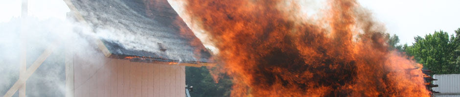
Based on the intermediate scale results, two wall/roof full-scale mockup assembly combinations were selected for six outdoor full-scale tests. Each of the mockups consisted of an external wall/roof combination. The first combination was plywood siding wall and asphalt shingle covered roof. The second combination was vinyl siding wall and cedar shake covered roof. The wall/roof angle was 45 degrees. Rhododendron plants were positioned in front of the mockup walls in all the tests. The wall assemblies were about 3.05 m high by 3.66 m wide, and were composed of wood studs the centers of which were 40.6 cm apart. The sheathing was 1.3 cm thick, oriented strandboard, and covered with “Tyvek” water barrier. Either standard vinyl siding (see Figure 5) or 13 mm thick plywood siding was installed as exposed surfaces following the standard construction methods. The roof assemblies were about 3.66 m wide and 2.44 m deep. They were constructed very similarly, except that the sheathing was 16 mm thick and the external surfaces were either standard asphalt shingles or cedar shakes. The mockup assemblies are shown in Figures. 3 – 5. The wetting agents, the drying times, conditions during the drying period, and the design exposure fluxes used for various tests are shown in Table 2. It should be noted that the exposure fluxes on most of the roof surface were expected to deviate from the wall flux exposures because of the geometry of the mockups.
The design exposure fluxes applied in each test were determined based on the intermediate scale test results1. The smaller CFFG of the two building assemblies for the particular wetting agent and drying condition was used for the full scale tests.
The exposure fluxes to the mockups were provided by burning stacks of weathered wood pallets. Although the pallets, their number, and arrangement were as similar as possible, differences in actual fluxes from the design were expected and measured as described in the Results section of this paper. The dimensions of the stacks, the dimensions of the mockups, and the test experimental setup are shown in Figures 3 – 5.
Table 2 Full-scale tests of two wall/roof combinations with various wetting agents
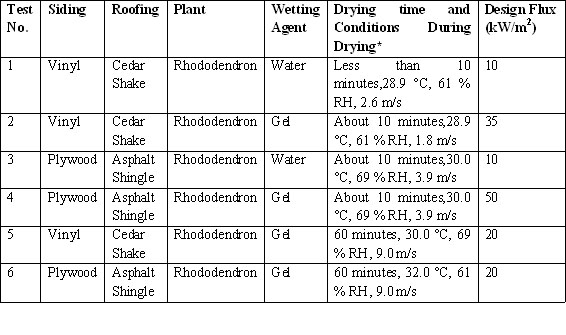
*Average ambient temperature, relative humidity (RH), and wind speed during the time of the wetting agent drying
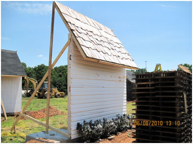
Figure 3 Experimental setup of a full-scale test (vinyl siding and cedar shake roof mockup shown in the photograph)
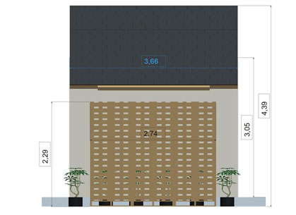
Figure 4 Front view of the experimental setup showing the wood pallet stacks in the front and the wall/roof assembly in the back
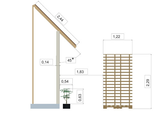
Figure 5 Side view of the experimental setup
The external wall and roof assembly mockups were constructed by a local contractor who used the same manufacturer and types of products as used in the intermediate scale tests. About 0.91 m of the roof was extended beyond the wall. The assemblies were positioned on horizontal concrete slabs and braced as shown in Figure. 3. Six rhododendron plants in 26.5 liter pots were buried in front of the wall assemblies as shown in Figures 3-5 so that parts of the plants touched the walls. The plants had been conditioned to 20±5% of water content before the tests were conducted to simulate water-starved but still alive plants.
The wood pallet stacks were positioned in front of the mockup parallel to the wall. The distance between the wood pallet stacks and the mockup wall varied based on the desired flux exposure as shown in Table 2. The distances were determined based on the flux exposure calibration procedure described in the “Description of Tests” section below.
Instrumentation
Each mockup was instrumented with two 12 mm diameter water cooled Schmidt Boelter type heat flux gauges (HFG) of 100 kW/m2 range and 11 Type K, 0.51 mm thermocouples (TCs). The HFGs were positioned in the center of the wall, and in the vertical centerline of the roof about 1.0 m from the lower edge. The HFGs were installed in the holes pre-drilled in the assemblies so that the sensing surfaces were flush with the exposed wall siding surface and the roofing surface. Nine TCs were installed on the wall siding surface and two on the roofing surface so that the TC junctions were in contact with the surfaces. The locations of the HFGs and thermocouples on the wall are shown in Figure 5. The TCs were covered with the wetting agents prior to the tests. The HFGs were not covered with the wetting agents (the sensing surfaces were protected during the wetting agent application) except for Test 2. The HFG readings during this test reflect the fact that they were covered by the gel until it evaporated.
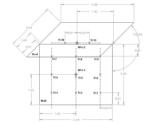
Figure 6 The locations of the TCs and the HFG on the wall
Description of Tests
Calibration of heat flux/distance relationship
The flux (mainly radiation heat) was provided by flames and hot surfaces from burning wood pallets arranged in three stacks. The wood pallet stacks and their arrangement are shown in Figures 5-7. A calibration test was conducted where two water cooled Schmidt Boelter type heat flux gauges of 100 kW/m2 range were positioned at 1.1 m height at 2 m and 4 m distances in front of the burning pallet stacks. The measured fluxes were recorded. The distances for the required wall heat flux exposures were calculated based on the two predetermined distances, the measured fluxes at those distances taking the changing radiation view factor into account, and assuming that the radiator (burning pallet stacks) surface temperature and emissivity were constant. The flux exposures followed a polynomial function of the distances. The distance for the 50 kW/m2 exposure was 0.8 m, the distance for the 35 kW/m2 exposure was 1.6 m, the distance for the 20 kW/m2 exposure was 2.2 m, and the distance for the 10 kW/m2 exposure was 3.5 m. The exposure fluxes on the roof were not calibrated and were expected to vary over the roof area.
Application and drying of wetting agents
Water was sprayed on the parts of the mockups using a garden hose spray nozzle for at least one minute. The gel was applied by using the garden hose applicator that was provided by the gel manufacturer. The gel manufacturer instructions were adhered to for the application. The gel was applied until the surfaces looked white (the gel was about 4 mm thick). Special care was taken when the gel was applied to the mockup edges and underneath the roof overhangs. Tests 1-4 were conducted within 10 minutes of applying the wetting agents. The drying conditions were the current weather conditions. Tests 5 and 6 were exposed to drying conditions for 60 minutes before the exposure to the flux from burning pallets. The drying conditions for these two tests were similar to those described as “severe drying conditions” for the intermediate scale tests. The wind velocity was provided by two large fans positioned so that the wind velocities over the wall parts of the mockups were as close as possible to 9 m/s, and as uniform as possible. The wind velocities were measured by a handheld rotating vane Anemometer. The heat fluxes from the sun during the drying periods were not measured. The ambient temperatures and relative humidity are given in Table 2 in the “Results” section of this paper.
Description of tests
For each test, the pallet stacks were placed in front of the mockup at a distance required for a desired flux exposure on the wall. This resulted in a somewhat higher exposure of the overhung part of the roof, and lower exposures of most of the roof beyond the wall. The flux received by the plants was probably close to the desired flux since the effects of lower view factors at the bottom of the walls were compensated by a shorter distance of parts of the plants to the burning pallet stacks.
Two ASTM E108 Type B brands were used as ignition sources in each test. One brand was positioned underneath the plant that was the closest to the middle of the bottom of a wall. The position of this brand was adjusted so that the flames from the burning brand would impinge directly onto some plant leaves and branches. The other brand was positioned with its center approximately 20 cm from the bottom edge on the vertical axis of the roof. The brands were sprayed with some diesel fuel and ignited shortly before the wood pallets were ignited.
The wood pallet stacks were also uniformly sprayed with diesel fuel to insure quick flame spread over the pallets, and as uniform burning of the pallet stacks as possible. About 15.2 kg of diesel fuel was used for each test. The pallets were ignited at several locations along the bottom of the stacks on the side facing the mockup. The ignition of the pallets was considered the start of each test.
REFERENCES
[10] Ettlinger, M.G., Beall, F.C., Development of a laboratory protocol for fire performance of landscape plants, International Journal of Wildland Fire, 13, p. 479-488, 2004.
[11] ASTM E 1623-07, “Test Method for Determination of Fire and Thermal Parameters of Materials, Products and Systems Using an Intermediate Scale Calorimeter (ICAL)”, 2007 Annual Book of ASTM Standards, Vol. 04.07.
[12] Cohen, J.D., Butler, B.W., Modeling Potential Structure Ignitions from Flame Radiation Exposure with Implications for Wildland/Urban Interface Fire Management, Proceedings of 13th Fire and Forest Meteorology Conference, Lorne, Australia 1996.


